Beyond the Online Tool: Why Understanding the ‘How’ Matters
In the era of digitalization, the answers are never far. A simple Google search of a pneumatic cylinder force calculator will reveal thousands of tools that will provide an answer with little effort and in a matter of seconds. It is quick and easy, but when these tools are used without knowing the calculations involved, it can be risky. The calculator is only as good as the data entered. When something unforeseen happens—a small rise in load, a fall in line pressure from the compressor, or some unexpected friction force—the simple, context-free number on the calculator is not used much. The outcome may be stagnant equipment, broken clamps, or halted processes, resulting in expensive downtimes and redesigns.
This guide decomposes the principles behind those calculations and describes the physics that governs the force of a pneumatic cylinder, produced by compressed air. It is aimed at engineers, designers, and technicians who not only want to know the right answer but also want to know where the answer is. You will not only be able to use a calculator by the end, but you will be able to do the calculations yourself, identify the variables at play, and make informed and sound design decisions regarding the cylinder force.
Meet the Force Generator: A Quick Look at Pneumatic Cylinders
We will not get into the mathematics yet, but first we will look at the part that causes the force, the pneumatic actuator. A pneumatic cylinder is a mechanical actuator that uses the potential energy of compressed air pressure to provide linear motion. It is a basic element of industrial automation, and it is used to clamp, push, pull, lift, and press in millions of applications. The general term pneumatic refers to any system using gas or pressurized air.
It is important to understand the two main types of cylinders because it determines the way we calculate the pneumatic cylinder force.
Single-Acting vs. Double-Acting Cylinders
- Single-Acting Cylinders (SAC):Single-acting cylinders are cylinders that are powered by compressed air to exert force in one direction only, usually the push or outward stroke. One port is used to admit air into the cylinder, which drives the piston. The release of the air pressure causes the piston to be restored to its initial position by an internal spring or an external load. They are simple and therefore reliable and economical to use in applications such as clamping or ejecting parts where force is required in only one direction.
- Double-Acting Cylinders (DAC): These are more general. This type of cylinder is a two-port device with two ports at each end. One port is pressurized with air to extend the piston rod and the other port is pressurized to retract it during the return stroke. This gives powered movement in either direction. This dual control necessitates their use in applications where both a controlled push and a controlled pull are required, e.g. positioning a component or operating a valve. Among the various types of air cylinders, these are also known as piston rod cylinders. There are also rodless cylinders, which generate motion differently but are beyond the scope of this particular guide.
To make our calculations in this guide, we will mainly use the double-acting cylinder because it involves both push and pull forces. The push force principles, however, also apply to single-acting pneumatic cylinders.
The Core Formulas: The Math Behind Every Calculation
*This video is On force calculation of pneumatic cylinder complete calculation with example.
The mathematics of pneumatic force are simple and are based on a fundamental law of physics: Pressure = Force/Area (PA). Rearranging this, we obtain the basic formula of our calculations:
Force = Pressure × Area
This is the formula for all pneumatic cylinder force calculations. How does it work in the two different actions of a cylinder?
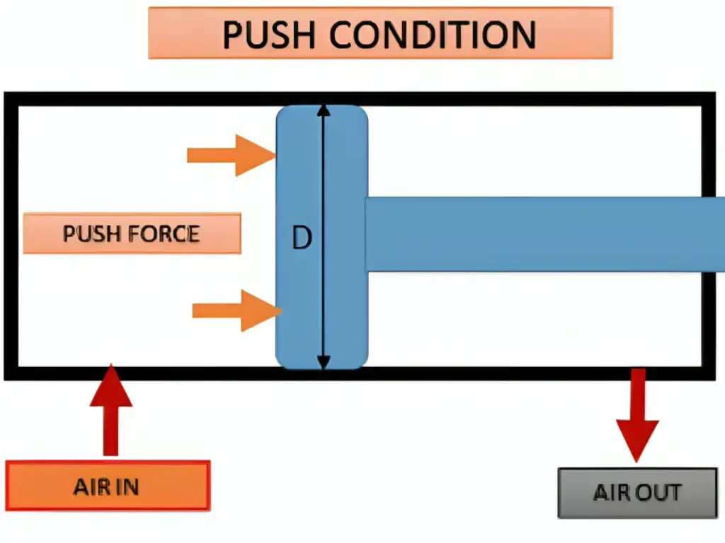
Calculating Push Force (The Extend Stroke)

As a cylinder is extended, the compressed air is pushing on the full face of the piston. Thus, the Area in our formula is the complete circular area of the bore (the internal diameter of the cylinder).
The equation is: Force = Pressure × (π × (Bore Diameter/2)²)
Suppose we take an example of a cylinder that has:
- Bore Diameter: 50 mm (The piston diameter is the same as the bore diameter)
- Operating Pressure (Cylinder Pressure): 6 bar (or 0.6 N/mm²)
The area of the piston is first calculated:
- Area = π × (50 mm / 2)²
- Area = 3.14159 × (25 mm)²
- Area = 3.14159 × 625 mm²
- Area = 1963.5 mm²
Compute the force now:
- Push Force = 0.6 N/mm² × 1963.5 mm²
- Push Force ≈ 1178.1 N
At 6 bar of pressure, a 50mm bore cylinder has the theoretical ability to push with a force of about 1178 Newtons.
(Insert infographic of air pressure on the entire face of the piston)
Calculating Pull Force (The Retract Stroke)

The situation is different when the cylinder retracts. The rod-end port is now opened to the compressed air, which pushes the piston to draw the rod back in. But the piston rod itself is fastened to this face of the piston and takes up space. This implies that the area that the air can act on is decreased. The effective area, or F effect, is the area of the piston less the cross-sectional area of the rod.
The equation is: Pull Force (F) = Pressure (P) × (Piston Area – Rod Area)
Suppose we take the same cylinder as before, and put in a piston rod:
- Bore Diameter: 50 mm (Piston Area ≈ 1963.5 mm²)
- Rod Diameter: 20 mm
- Operating Pressure: 6 bar (0.6 N/mm²)
To begin with, find the area of the rod using its diameter:
- Rod Area = π × (20 mm / 2)²
- Rod Area = π × (10mm)²
- Rod Area ≈ 314.16 mm²
The effective area of the retract stroke is now found:
- Effective Area = 1963.5 mm² – 314.16 mm²
- Effective Area = 1649.34 mm²
Lastly, compute the pull force:
- Pull Force = 0.6 N/mm² × 1649.34 mm²
- Pull Force ≈ 989.6 N
As shown, the pull force is significantly lower than the push force, which is an important factor in any design.
(The area of the piston is smaller because of the rod – Placeholder for an infographic)
From Theory to Reality: The Hidden Factors That Impact Force
The theoretical force is given by the formulas we have just discussed. It is an ideal-world figure, a computation under ideal circumstances. Industrial conditions are not perfect and they add elements that diminish the theoretical force before it can do any useful work. A professional engineer does not merely compute the theory; he or she predicts reality.
- Friction and Efficiency: This is the main factor. All pneumatic cylinders have seals—piston seals, rod seals, and wipers. They are necessary to hold compressed air, yet they cause friction when the piston and rod move. This friction acts against the movement and decreases the net output force. Moreover, the guide bands of the piston rub against the cylinder barrel. As a thumb rule, you can anticipate these frictional losses to eat up 10-25 percent of your theoretical force. This percentage may be even greater in low-pressure or very slow-moving applications. That is why Safety Factor is necessary. The usual thing to do is to estimate your needed force and multiply it by a factor of 1.25 (or greater) to get the needed theoretical force that your cylinder will have to generate.
- Operating Conditions: Other factors may also impair performance. Resistance can be caused by back pressure in the exhaust line. Friction and wear can be dramatically increased by side loading (a force applied perpendicular to the piston rod). The viscosity of the lubricant can even vary with temperature, and this can alter the performance of the seals.
Step-by-Step Example: Sizing a Cylinder for a Clamping Application

Diagram Elements (Legend):
| Component | Description |
| Wooden Block | The workpiece to be clamped during drilling |
| Pneumatic Cylinder | Pushes the block horizontally using pressurized air |
| Compressed Air (5 bar) | Factory air supply driving the cylinder |
| Clamp Force Arrow | Indicates direction of force (500 N) with safety factor applied |
| Safety Factor | 1.25 applied to the original 400 N requirement for reliability |
Now, we can use this knowledge in a practical situation. Consider that you have to design a horizontal clamping device to clamp a wooden block to perform a drilling process.
- State the Requirement: The clamping mechanism should exert a minimum continuous force of 400 N on the block to keep it in place.
- Consider Reality (Apply Safety Factor): We are aware that friction is a factor. We will apply a safety factor of 1.25 to guarantee reliability.
- Theoretical Force Required = 400 N × 1.25
- Theoretical Force Required = 500 N
- Identify System Pressure: The factory compressed air system has a constant operating pressure of 5 bar (0.5 N/mm²).
- Compute Piston Area Required: We shall use push stroke to clamp. We re-arrange our fundamental equation: Area = Force / Pressure.
- Required Area = 500 N / 0.5 N/mm²
- Area Required = 1000 mm²
- Find the Cylinder Bore: We now determine the diameter of the bore which gives at least this area. We apply the area formula Area = π × (Bore/2)² and solve for the bore.
- 1000 mm² = π × (Bore/2)²
- 1000 / π = (Bore/2)²
- 318.3 = (Bore/2)²
- √318.3 = Bore/2
- 17.84 mm = Bore/2
- Bore = 35.68 mm
- Choose a Standard Cylinder: Pneumatic cylinders are available in standard bore sizes. The standard size above 35.68 mm is usually 40 mm.
Example Conclusion: In order to be able to deliver a 400 N clamping force with a 5 bar air supply, we would choose a standard pneumatic cylinder with a 40 mm bore. Selecting the next smaller size, a 32 mm cylinder, would not be enough when friction in the real world is taken into account. This systematic procedure makes the design strong.
Hebai-Omch: Why Cylinder Quality Matters for Real-World Performance
At Hebai-Omch, we fully understand how critical cylinder quality is to real-world performance. No matter how precise your calculations are, if the cylinder itself has large tolerances, poor sealing, or a short lifespan, your entire design can fail when put to the test. That’s why we strictly control the inner diameter tolerances and surface finish during manufacturing, ensuring that the actual effective area of our cylinders is nearly identical to theoretical values. Every cylinder we produce is precision-machined to deliver accurate and consistent force output across various pressure levels, with minimal deviation. Additionally, our cylinders maintain high performance throughout a lifespan ranging from 3 million to 10 million cycles, ensuring your equipment runs more stably and reliably.
Our sealing technology is equally dependable. Hebai-Omch cylinders use high-performance seals that significantly reduce friction and leakage, enhancing overall energy efficiency. At the same air pressure, you’ll find that our cylinders deliver more stable and powerful force. This translates to greater productivity and reduced energy waste. WithIP65, IP67, and even IP68 protection ratings, our cylinders continue to perform at a high level even in dusty, humid, or otherwise harsh environments,a key reason why over 72,000 customers worldwide have chosen to trust Hebai-Omch.
In addition, many customers overlook crucial details when selecting and sizing cylinders — such as accounting for side loads, high-frequency impacts, or special installation conditions — which can severely compromise cylinder performance on site. Hebai-Omch offers a wide selection of bore sizes from Ø12 mm to Ø320 mm, and custom stroke lengths from 10 mm to 2000 mm, meeting the needs of even the most complex applications. We also provide expert selection guidance for every customer, helping you avoid common pitfalls in sizing and load estimation so that your equipment performs as efficiently and durably in practice as it was designed to.
Common Pitfalls to Avoid When Calculating and Sizing
Knowledge is not just about knowing what to do, but also what to avoid. As you move forward with your own designs, be wary of these common errors that can undermine a project.
- Forgetting the Safety Factor: This is a primary error in cylinder sizing. Always assume there will be friction and unexpected loads. Sizing a cylinder for the exact calculated force is designed for potential failure.
- Using Peak Pressure for Calculations: A compressor might be rated for 10 bar, but the stable operating pressure at the point of use is often lower due to regulators, filters, and line losses. Use realistic, sustained pressure for your calculations, not an optimistic peak value.
- Ignoring Acceleration: According to Newton’s second law, the force required to accelerate a mass is greater than the force required to keep it moving at a constant velocity. If your application involves moving a significant weight, you must calculate the additional force needed for acceleration, or your cylinder may be undersized.
Conclusion: From Calculation to Confident Application

We began this journey by questioning the limits of relying solely on online sizing tools. From there, we unpacked the underlying formulas, factored in real-world variables like friction, and applied the theory to a practical example. What you now hold isn’t just a set of equations — it’s a complete methodology. You’ve gained the clarity to move confidently from system requirements to accurate calculations, and ultimately, to sound engineering decisions.
But even the most accurate calculation is only as good as the components that realize it. That’s where Hebai-Omch comes in. Our pneumatic cylinders are engineered to translate your design precision into dependable field performance. With tightly controlled inner diameter tolerances, advanced sealing technology, and industry-leading durability, our cylinders ensure your system performs exactly as intended — cycle after cycle, under real-world conditions.
When you’re ready to turn design into reality, Hebai-Omch is here to support you. From standard models to fully customized solutions, our team is equipped to help you select or engineer the right cylinder for your exact needs. Explore our product line or connect with our engineers today — and let’s build something exceptional, together.